
Electrical Troubleshooting
Technicians measure voltage at multiple points along each branch circuit, check for thermal signatures at connections, and isolate the exact location of opens or ground faults using continuity and impedance tests.
Electrician · the USA
All Tech Electric performs Electrical Repair across the USA through systematic circuit tracing, load verification, and targeted fixes to restore power safely.
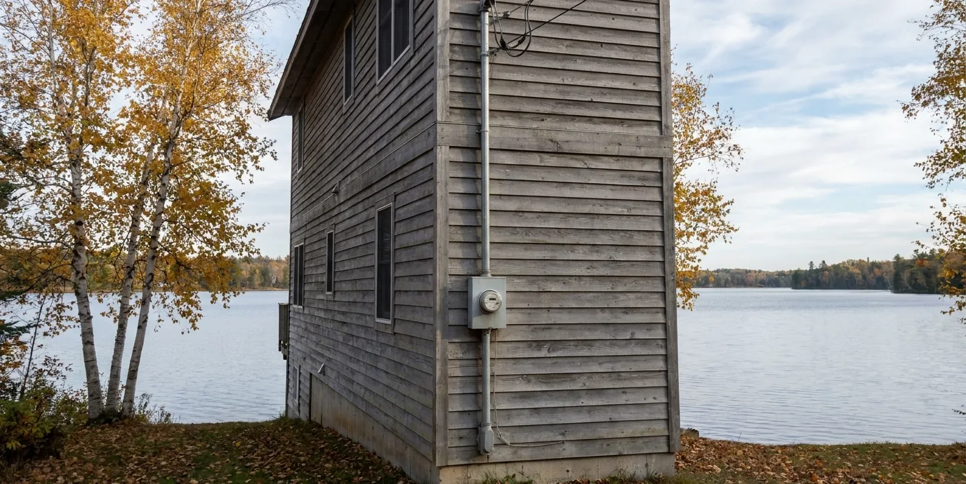
Technicians start at the panel and follow each conductor to locate opens, shorts, or high-resistance joints before any replacement.
Voltage drop tests and ground impedance measurements confirm whether the fault lies in wiring, devices, or the service entrance.
Each breaker is exercised and main bonding jumpers inspected to ensure proper fault current paths exist after the repair.
Our technicians address specific electrical tasks with targeted methods that match the requirements of each circuit, device, or system component.
Technicians measure voltage at multiple points along each branch circuit, check for thermal signatures at connections, and isolate the exact location of opens or ground faults using continuity and impedance tests.
We evaluate bus bar condition, torque all terminations, verify main breaker coordination with downstream devices, and transfer circuits while maintaining phase balance across the new service equipment.
Existing conductors are mapped room by room, junction boxes are added at required intervals, and new NM or MC cable is pulled with proper support spacing and staple placement to meet code spacing rules.
Each GFCI is wired to protect downstream receptacles, line and load terminals are identified correctly, and the device is tested with both push-button and external fault simulation tools.
We verify ceiling box support rating, install rated fan-rated boxes where needed, balance blades after mounting, and terminate the separate neutral conductor required by current code.
Transfer switches are sized to the generator output, interlock kits prevent backfeed, and load calculations determine which circuits remain on the generator side during utility outage.
Our technicians examine service entrance conductors, check torque on all lugs, verify grounding electrode systems, and document panel fill and circuit labeling conditions.
Low-voltage transformers are placed on GFCI-protected circuits, wire gauge is selected by run length to limit voltage drop, and fixtures are aimed to avoid glare into neighboring properties.
Repeated breaker trips on the same circuit usually point to either an overloaded branch or a developing short in a receptacle or appliance cord. Technicians trace the circuit from the panel outward, noting any shared neutrals or multi-wire branch circuits that can mask the true load. Dimming when large motors start indicates voltage drop caused by undersized conductors or loose terminations at the panel or meter base.
Burn marks around outlets or switches signal arcing from loose terminal screws or back-stabbed conductors. These conditions require immediate isolation of the affected circuit at the breaker before further damage occurs to the wiring insulation or surrounding materials.
Turn off the breaker that supplies the affected area rather than resetting it repeatedly. Note which lights or receptacles lose power so the pattern can guide later testing of shared neutrals or multi-wire branches. Avoid using the space until the circuit is confirmed safe.
If an odor of burning insulation is present, leave the area and do not attempt to locate the source with additional loads or test equipment until power is removed at the main breaker.
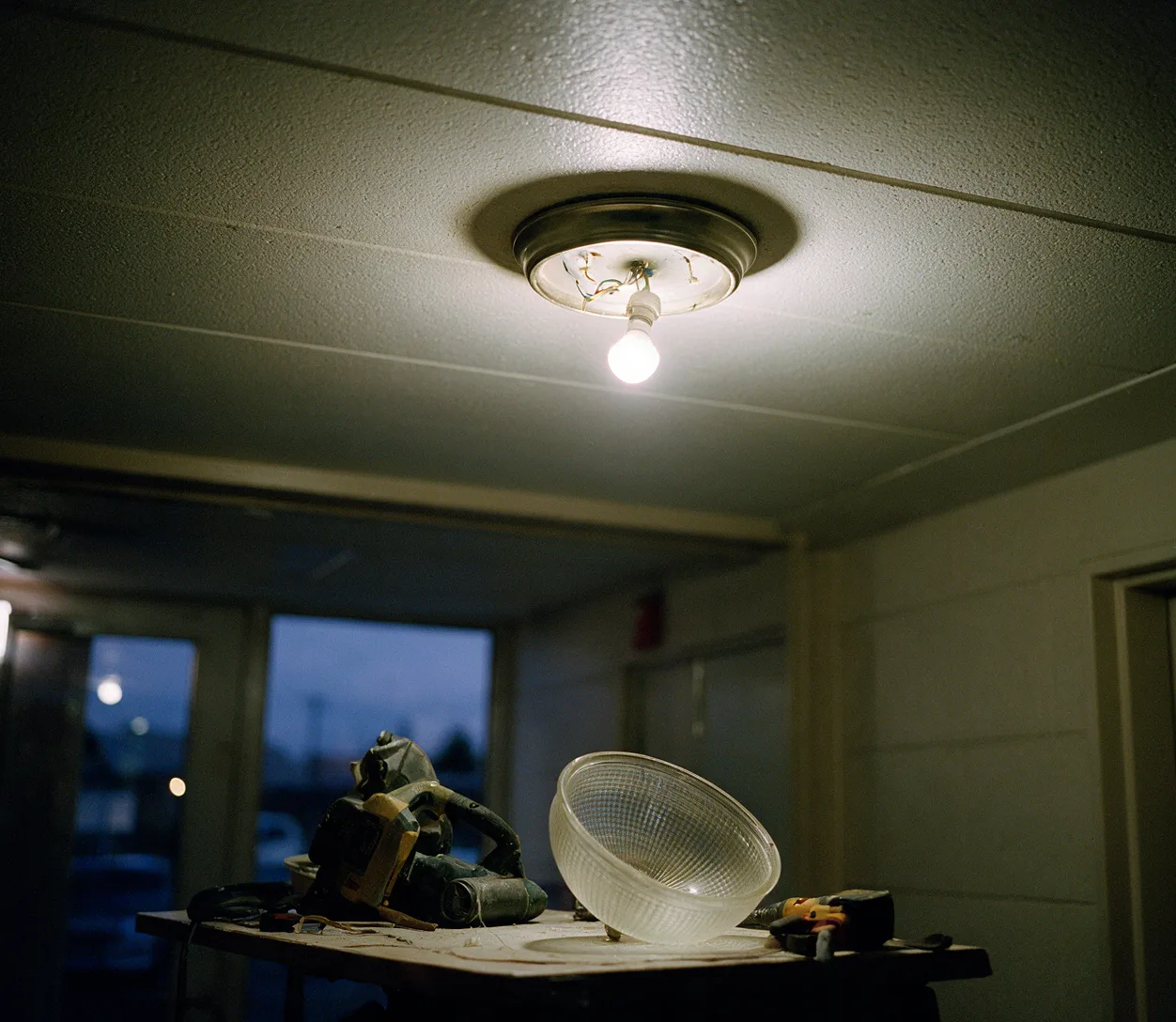
We follow a repeatable sequence that isolates the electrical issue, restores safe operation, and verifies the repair before leaving the property.
Technicians open the panel, torque all terminations, and record breaker types, wire gauges, and any signs of overheating before proceeding to the reported fault location.
Each affected branch is de-energized, conductors are tested for continuity and insulation resistance, and the exact fault point is marked on a simple diagram for the property owner.
Loose connections are tightened or replaced, damaged conductors are spliced with listed connectors, and any added junction boxes receive permanent access covers.
Voltage drop and ground impedance are rechecked under load, all breakers are exercised, and the homeowner receives a written summary of what was corrected.
Technicians first confirm zero voltage with a calibrated meter at the panel and again at the point of work. They then open junction boxes to inspect splices for discoloration or loose wire nuts while measuring voltage drop under load on each leg.
After the fault is isolated, conductors are repaired or replaced, terminations are torqued to manufacturer specifications, and the circuit is re-energized while monitoring current draw and temperature rise at the repaired points.
Technicians compare the cost of localized conductor splicing against the labor required to pull new cable through finished walls. When multiple junctions show heat damage or when the original wiring uses aluminum conductors, full replacement of the branch often becomes the practical choice.
Panel replacement is recommended when the bus bars are pitted, when breaker types are obsolete, or when additional circuits are needed and physical space or bus rating prevents safe expansion of the existing equipment.
Cost is driven by the number of circuits involved, the accessibility of wiring runs behind finished surfaces, and whether the repair requires new cable pulls or can be completed with splices at existing boxes. Material choices such as copper versus aluminum conductors and the need for AFCI or GFCI protection also affect the scope.
Additional variables include the condition of the service equipment, the presence of multi-wire branch circuits that must be separated, and whether the work must occur in finished spaces that require patching afterward. These elements are assessed during the initial site visit so the scope remains clear before work begins.
Homes built before 1965 frequently contain cloth-insulated conductors or knob-and-tube wiring that has become brittle. Technicians identify these systems by examining accessible junction boxes and attic runs before planning any circuit modifications or additions.
In rental properties the focus is on documenting existing conditions at move-in, labeling all circuits clearly, and ensuring GFCI protection exists in required locations so future service calls can be addressed without repeated disruption to tenants.
A persistent trip indicates either sustained overload from added appliances or a developing short between conductors or to ground. Technicians measure resistance between conductors with the breaker off and inspect receptacles and junctions for damaged insulation or loose connections that allow current to bypass the intended path.
High inrush current from the compressor motor creates temporary voltage drop along undersized conductors or through high-resistance terminations. Measuring voltage at the panel and at the fixture while the motor starts reveals whether the drop originates in the service entrance, branch wiring, or a loose neutral connection.
Yes when the line and load terminals are wired correctly and the device is rated for the circuit amperage. The GFCI must protect all downstream receptacles on the same branch, and the test button must be verified to open the circuit before the installation is complete.
They examine insulation condition, count the number of heat-damaged junctions, and compare the labor of fishing new cable against the cost of repeated splices. When aluminum conductors or cloth insulation are present throughout the run, replacement is usually selected to avoid future failures.
Service entrance conductors, main bonding jumpers, grounding electrode connections, breaker types and fill, torque on all lugs, and the condition of accessible splices. Voltage drop under load and ground impedance are also recorded to identify marginal circuits.
Wobble results from an unbalanced blade set, a ceiling box that lacks proper support, or a mounting bracket not seated squarely against the box. Technicians check box rating first, then balance blades with provided weights after confirming the fan-rated box is securely attached to framing.
Contact All Tech Electric to schedule circuit tracing and targeted repairs that restore safe power in your property.