Our technicians begin every project by mapping the existing branch circuits and measuring current draw at each panel leg. This reveals whether an overload stems from undersized conductors, shared neutrals, or an imbalanced phase load. Once the measurements are recorded, we isolate the affected run and verify grounding continuity back to the main bonding jumper before planning corrective steps.
We then evaluate the service entrance rating against the calculated demand, checking for signs of overheating at lugs or bus bars. When grounding electrode resistance exceeds acceptable limits, we trace the path to determine if supplemental rods or a concrete-encased electrode will restore a low-impedance fault path without disturbing finished surfaces. Every service below is available from All Tech Electric across the USA.
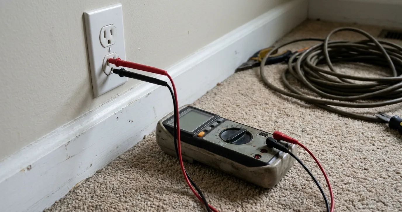
Technicians start by de-energizing the suspected branch and using a multimeter to confirm zero voltage at the load side of the breaker. Next we measure resistance along the hot and neutral conductors to locate opens or high-resistance splices, then re-energize under controlled load to observe voltage drop at the farthest outlet.
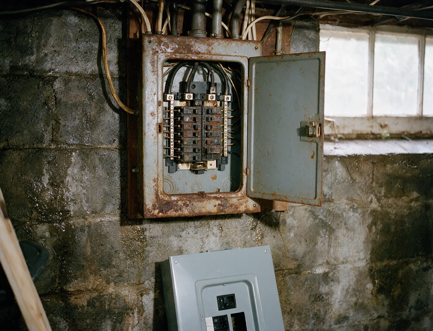
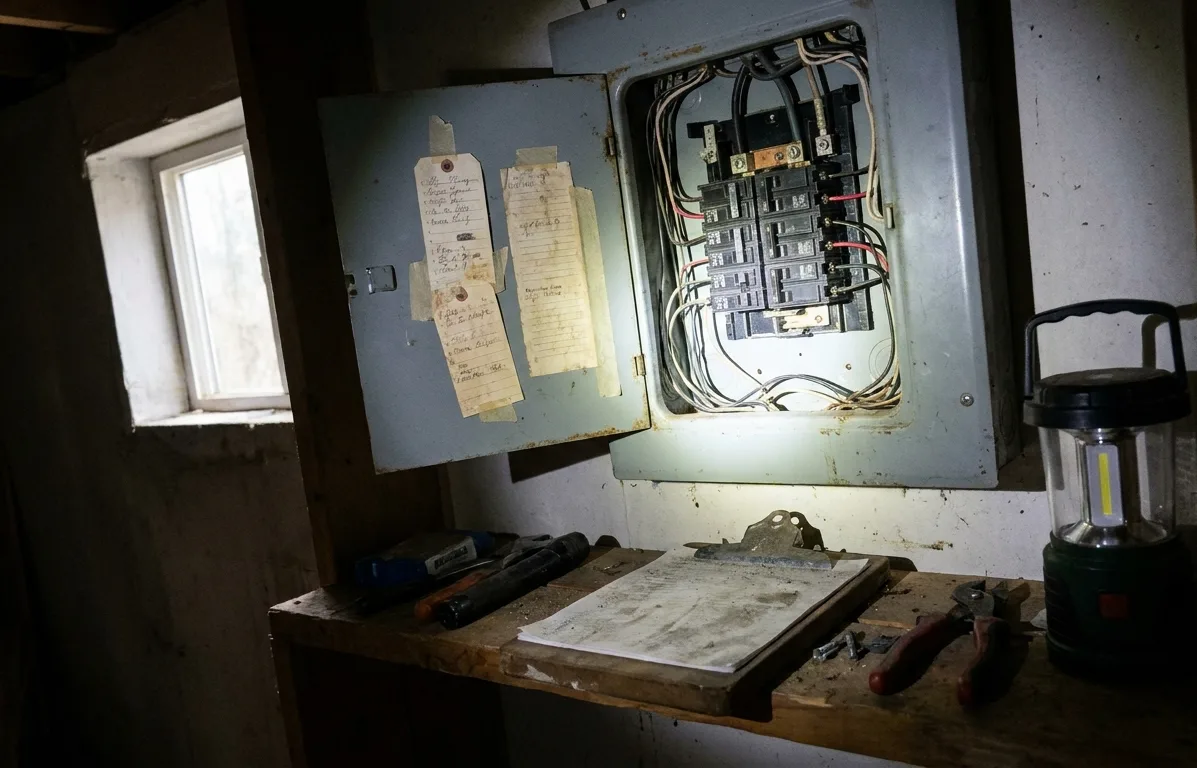
We first calculate the existing demand load on each leg to confirm the new panel rating. After removing the old enclosure, our technicians torque every new breaker connection to specification and verify that the equipment grounding conductor lands on the isolated bar, maintaining separation from the neutral bus.
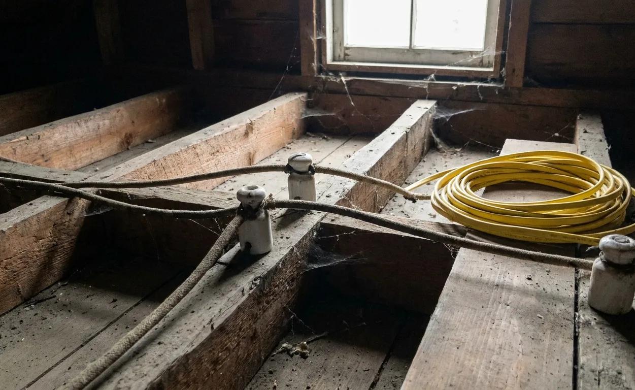
Work begins with a room-by-room inventory of receptacle and lighting circuits. We pull new 12 AWG or 10 AWG copper to dedicated runs, install AFCI breakers where required, and bond each metal box to the equipment ground so that any fault current returns quickly to the source.
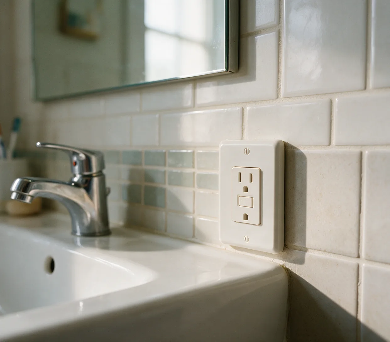
Our technicians identify the first receptacle on each branch that protects downstream devices. After confirming line and load terminals, we wire the device so that the test button interrupts both hot and neutral paths and the reset restores power only when no imbalance is detected between the conductors.
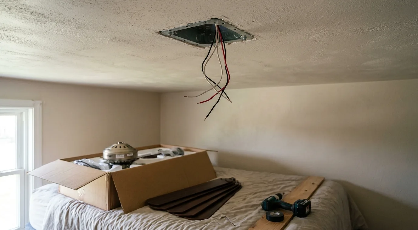
We verify that the existing box is rated for fan support by checking its labeling and securement to the joist. A separate equipment grounding conductor is landed at the fan bracket, and the speed-control switch is wired through the proper traveler so that the motor windings receive continuous power without shared neutrals.
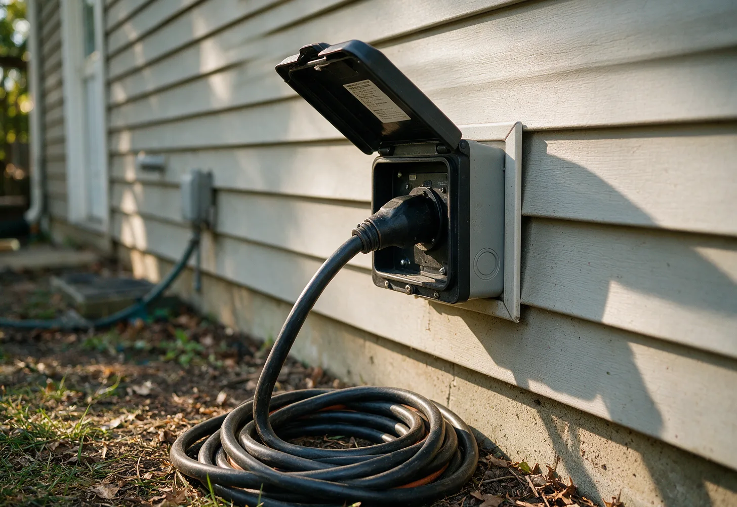
Technicians install a manual transfer switch that breaks the utility neutral and hot legs before connecting the generator. We size the feeder conductors for the generator output, bond the generator frame to the existing grounding electrode system, and confirm that back-feed cannot occur through any multi-wire branch circuit.
We methodically open each panel and junction box to inspect conductor insulation, torque values at terminations, and the condition of the main bonding jumper. Voltage is measured at multiple points under load to detect excessive drop that indicates loose connections or undersized neutrals.
Low-voltage runs are laid out so that each fixture receives its own tap from the main cable, avoiding cumulative voltage drop. Transformers are sized for the total wattage plus headroom, and the secondary is grounded only at the transformer case to prevent ground loops between fixtures.
Matching symptoms to service scope
Start by noting which protective device trips or which area loses power. If only receptacles in wet locations lose power while lighting remains, the issue points to GFCI protection. When the main breaker opens under heavy load or the panel shows signs of heat, panel replacement or load recalculation becomes the next step in the sequence.
Persistent voltage drop across multiple rooms or repeated AFCI trips usually indicates shared neutrals or undersized branch wiring. In those cases whole-home rewiring restores proper conductor sizing and dedicated neutrals. Generator hookup is required only when a portable or standby unit must supply selected circuits without back-feeding the utility supply.