
Panel Replacement in the USA
All Tech Electric technicians begin Panel Replacement by mapping the service entrance conductors and calculating total connected load against the existing bus rating. They isolate the meter base, remove the deadfront, and test each breaker under simulated draw to locate heat buildup or arcing at stab connections.
The process continues with verification of the grounding electrode conductor size and bonding jumper continuity at the panel. Technicians then select a new load center rated for the calculated demand, install torque-rated lugs on the main lugs or breaker, and re-terminate neutral and ground bars separately to meet current separation rules. Our technicians verify panel loads during panel replacement then point to All Tech Electric homepage covering the USA.
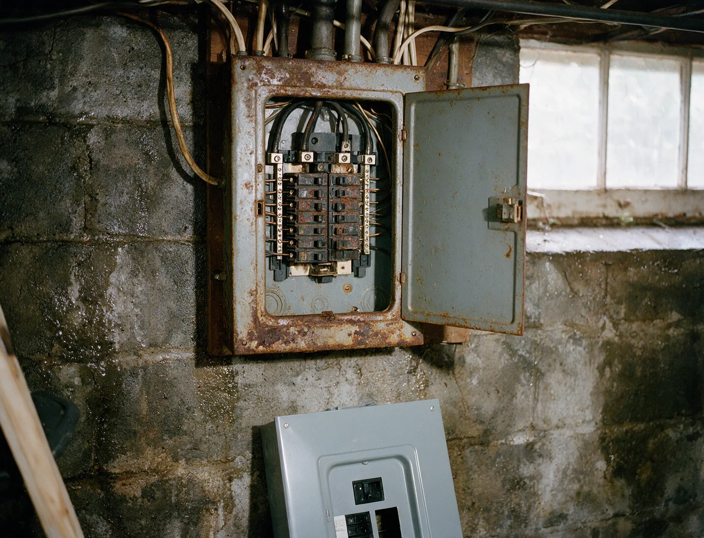
Observable Indicators of Panel Stress
- Breakers trip repeatedly on the same circuit under normal load.
- Scorch marks appear on the deadfront or around breaker handles.
- Lights dim or flicker when large motors start across multiple circuits.
- The panel enclosure feels warm to the touch during peak usage hours.
- Aluminum service wire shows oxidation at the main lug connections.
Common Causes Leading to Replacement
Added appliances such as tankless water heaters or EV chargers increase continuous load beyond the original 100-amp bus capacity. Over time the main breaker overheats, causing contact erosion and higher resistance that accelerates wear on the busing.
Older fuse boxes or split-bus panels lack sufficient spaces for modern AFCI and GFCI requirements. When circuits are doubled up on single breakers, the resulting imbalance produces nuisance tripping and localized heating that cannot be corrected by simple breaker swaps.
Measurements and Checks During Service
Technicians use a clamp meter to record individual circuit amperage and compare the sum against the main breaker rating under controlled conditions. They also perform a voltage drop test between the meter and the furthest outlet to identify undersized service wire before any panel work begins.
A megohmmeter verifies insulation resistance on the feeder conductors after the panel is isolated. Grounding electrode resistance is measured with a fall-of-potential tester to confirm the existing rod or plate meets the 25-ohm threshold or requires a supplemental electrode.
Materials Selected for the Upgrade
A copper-bus load center rated at least 200 amps replaces the original equipment. Tin-plated aluminum or copper lugs are torqued to manufacturer specifications, and new THHN conductors are pulled where existing wire shows signs of insulation degradation.
Arc-fault and ground-fault combination breakers are installed on all required circuits. A separate neutral bar is added if the existing panel bonded neutrals and grounds together, allowing proper separation while maintaining a single main bonding jumper at the service disconnect.
Actions Before Technicians Arrive
Homeowners should locate the main breaker and confirm it operates freely without binding. They must also note which circuits control critical loads such as refrigerators or medical equipment so power can be restored in stages after the new panel is energized.
All extension cords and portable generators must be disconnected from the premises wiring. This prevents back-feed during the transfer and allows technicians to de-energize the service safely at the meter without unexpected voltage present on the load side.
Panel Replacement questions
How long does Panel Replacement usually take?
Technicians isolate power at the meter, remove the old enclosure, mount the new load center, re-terminate all circuits, and perform torque verification plus insulation testing. The sequence typically requires four to six hours depending on the number of circuits and access to the service entrance.
Can the existing breakers be reused in the new panel?
Breakers are only transferred if they match the new load center brand, show no signs of heat damage, and pass mechanical operation tests. Otherwise new breakers are installed to ensure proper fit on the bus stabs and correct trip characteristics for each circuit.
What happens to the meter during the changeover?
The utility meter is removed after coordination with the serving utility. Technicians install a temporary jumper or use a meter socket adapter so the new panel can be energized and tested before the permanent meter is reinstalled and sealed.
Will circuits need to be labeled again after replacement?
Every circuit is traced and documented during the transfer. New directory cards are completed with updated descriptions that reflect actual connected loads, making future troubleshooting faster and reducing the chance of accidental shutdown of critical equipment.
Schedule Panel Replacement
Contact All Tech Electric to arrange a load calculation and panel assessment before adding new circuits or appliances.