
Generator Hookup in the USA
Our technicians begin every Generator Hookup by tracing the main service entrance conductors and identifying the neutral-to-ground bond location inside the panel. They then calculate running and starting wattage for each connected appliance so the transfer switch can isolate only essential circuits without exceeding the generator output rating. This step prevents overload trips and voltage drop across the feeder.
Next the crew measures the available breaker spaces and determines whether an interlock plate or a dedicated transfer switch provides the safest separation between utility and generator sources. They verify that the equipment grounding conductor remains continuous and that the generator frame bond matches the installation type required by the unit manufacturer. We measure amperage draw prior to generator hookup installation and add notes to All Tech Electric homepage in the USA.
Indicators That Generator Hookup Requires Attention
- Transfer switch fails to isolate utility and generator feeds
- Neutral bond creates parallel paths when generator runs
- Breaker trips immediately after generator start under load
- Voltage drop exceeds five percent on dedicated circuits
- Grounding electrode conductor shows corrosion or loose lugs
Initial Site Assessment
Technicians first locate the service disconnect and record the amperage rating of the main breaker. They open each branch circuit breaker one at a time while noting which loads share a leg so the transfer switch can be wired to keep both legs balanced during generator operation.
They also inspect the existing grounding electrode system and measure resistance to earth using a clamp-on tester. If resistance exceeds twenty-five ohms they document the need for an additional rod before any generator connection is made.
Load and Circuit Mapping
Each circuit is evaluated for both continuous and surge amperage. Motors in well pumps and air handlers are tested with a clamp meter during startup to capture locked-rotor current so the generator can be sized correctly without nuisance tripping of the transfer switch breakers.
Technicians then create a prioritized list of circuits that must remain energized and mark the corresponding breakers with colored tape. This list determines whether a whole-panel or sub-panel transfer switch is required to stay within the generator continuous rating.
Equipment and Material Choices
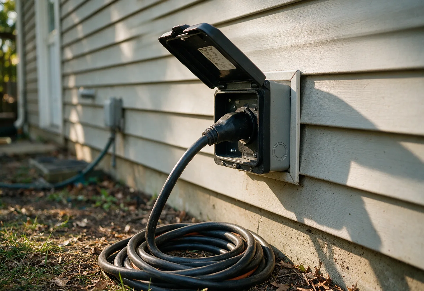
For portable generators an inlet box rated for the plug style is mounted on the exterior wall and fed with UF or THWN conductors sized according to the generator output. An interlock kit is installed on the panel cover so the main breaker and generator breaker cannot be closed simultaneously.
When a standby unit is used a listed automatic transfer switch with contactors rated for the full load is mounted near the panel. The switch includes provisions for a separate neutral bus so the generator can maintain its own bond without creating a parallel path back to the utility transformer.
Final Verification Steps
After conductors are landed the crew performs a polarity check and confirms that the generator neutral disconnects from the utility neutral when the transfer switch is in the generator position. They then run the generator under load while monitoring voltage and frequency at the farthest receptacle.
Any shared neutral that could create a hazard is separated and each circuit is retested for proper operation. The homeowner is shown the manual transfer procedure and the location of the interlock lever or switch handle before the job is complete.
Generator Hookup questions
What does a technician check first during Generator Hookup?
The technician opens the panel and records the main breaker size then maps which circuits share each leg. They measure grounding electrode resistance and verify that the neutral bond is located only at the service disconnect before any generator conductors are connected.
How is generator size determined for the home?
Each circuit is tested individually with a clamp meter to capture running and motor-start amperage. The total is compared against the generator nameplate rating so the transfer switch can be wired to only those loads that remain within continuous capacity without voltage drop.
What parts are typically required for a safe hookup?
An inlet box or automatic transfer switch, properly sized THWN or UF conductors, an interlock kit or listed transfer equipment, and a grounding electrode conductor extension if resistance exceeds twenty-five ohms. All components are selected to match the generator plug and panel amperage.
What should a homeowner do before the crew arrives?
Turn off all non-essential breakers and list the appliances that must stay powered during an outage. Note the generator model and plug style so the correct inlet or transfer switch can be prepared in advance of the site visit.
Schedule Generator Hookup
Contact All Tech Electric to arrange a load assessment and transfer switch installation for your generator.