
Whole-Home Rewiring in the USA
Our technicians begin Whole-Home Rewiring by mapping every circuit from the service entrance to the farthest outlet. They record amperage draw under load, note voltage drop along runs, and identify aluminum or undersized copper conductors that no longer meet modern demands. This systematic approach locates points where insulation has cracked or connections have oxidized before any walls are opened.
Replacement proceeds one circuit at a time so power can remain available in unaffected areas. New 12 AWG or 10 AWG copper THHN conductors are pulled through existing or enlarged raceways, terminated on fresh breakers, and bonded to the grounding electrode system. AFCI protection is added at the panel for sleeping rooms while GFCI protection covers required wet locations. Voltage drop calculations accompany whole-home rewiring work by All Tech Electric and appear on the homepage for the USA.
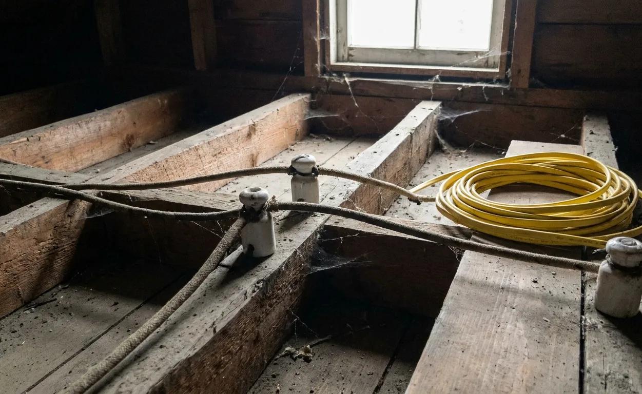
Indicators That Whole-Home Rewiring Is Required
- Breakers trip repeatedly when multiple appliances share one circuit.
- Two-prong receptacles show no equipment grounding conductor path.
- Lights dim noticeably when a large motor starts on the same branch.
- Warm or discolored outlet plates indicate loose terminations under load.
- Knob and tube or cloth-insulated wiring remains visible in attic spaces.
Common Causes of Wiring Failure
Over time, thermal cycling loosens screw terminals and oxidizes aluminum splices, raising resistance until heat builds enough to degrade insulation. Undersized conductors installed for earlier lower loads now carry continuous current near their rating, accelerating aging. Rodents chew through sheathing in attics and walls, exposing bare conductors to potential arcing.
Moisture intrusion around exterior penetrations corrodes ground wires and neutral bars inside the service panel, creating high-impedance return paths that elevate voltage on grounded equipment. These conditions remain hidden until a thermal scan or torque test reveals the defect.
Inspection and Measurement Sequence
Technicians first verify service capacity by measuring incoming conductor size and main breaker rating, then calculate the existing demand load using the standard optional calculation method. Each branch is isolated at the panel and tested for insulation resistance with a megohmmeter at 500 volts to locate compromised sections without energizing the circuit.
Grounding electrode resistance is checked with a fall-of-potential meter, and equipotential bonding is confirmed at metal water pipes and structural steel. Voltage drop is recorded at the farthest receptacle on each run under a 15-amp simulated load to determine which circuits require larger conductors or additional home runs.
Materials and Installation Choices
NM-B cable with 90-degree rated conductors is selected for dry interior locations while UF-B is used for underground or wet areas. Metal-clad cable provides additional physical protection in exposed garage or basement runs. All new devices carry tamper-resistant shutters and are rated for 20 amps where circuit capacity allows.
Panel upgrades accompany rewiring when the existing enclosure lacks sufficient breaker spaces or contains obsolete fuse blocks. A new main-lug or main-breaker panel with copper bus bars accepts AFCI and dual-function breakers without derating adjacent circuits.
Homeowner Preparation Before Arrival
Clear access to the main panel, attic hatch, and crawl space by moving stored items at least three feet away from these points. Note which rooms lose power when specific breakers are switched off and provide a written list of circuits that have tripped in the past month. Shut off power to any known damaged outlets and mark their locations with tape.
Identify appliances that must remain operational during the project so technicians can schedule work around those loads. Verify that furniture can be shifted away from walls that will be opened for cable routing. These steps allow the crew to begin testing immediately upon arrival.
Whole-Home Rewiring questions
How long does Whole-Home Rewiring take?
Duration depends on home size, number of circuits, and whether walls must be opened or fished from existing openings. A two-story residence with accessible attics typically requires three to five working days once mapping and material staging are complete.
Can circuits be added during rewiring?
Yes. After calculating available service capacity, additional home runs can be installed to kitchens, bathrooms, or workshops that previously shared overloaded branches. Each new circuit receives its own dedicated breaker sized to the conductor ampacity.
What happens to the existing wiring?
Abandoned conductors are disconnected at both ends, labeled, and left in place if removal would require extensive demolition. Where possible they are pulled out to reduce future confusion during later renovations or inspections.
Is power interrupted for the entire project?
No. Work proceeds room by room or circuit by circuit. Temporary extension cords from unaffected areas maintain power to refrigerators, medical equipment, and essential lighting while each branch is replaced and tested.
Plan Whole-Home Rewiring
Contact All Tech Electric to schedule a circuit mapping and load assessment for your property.